
Introduction :
-
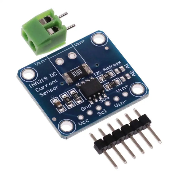
The INA219 DC Current Measurement Module can measure high-side current and voltage of up to 3.2A with 0.8mA resolution at voltages of up to 26VDC.
Package Includes:
- INA219 DC Current Measurement Sensor Module
- 6-pin Male Header
- 2-pin Screw Terminal Block
Key Features of INA219 DC Current Measurement Module:
- Measures current on the high side of the load
- Current measurements of up to 3.2A with 0.8mA resolution using a 12-bit DAC
- Load voltage of 0-26VDC
- I2C interface
- 3.3 and 5V logic compatible
Power Connections
The INA219 DC Current Measurement Module is inserted on the high side of the load, between the load and the load positive (+) power supply. This load power supply can range from 0V up to 26V.
The module itself is powered from 3-5V, so it is usually powered directly off the MCU.
The modules 3-5V logic supply should not be shared with motors running off the same voltage or else the device may reset due to electrical noise. If this happens, additional filter capacitance on the Vcc can be added near or on the module to try to minimize the problem.
Note that the INA219 module ground needs to be in common with the load ground or the voltage measurements will not be correct though the current measurement will be correct. If you don’t care about the voltage measurement, the grounds can be kept separate.
Current Sensing
The module uses a 0.1 ohm 1% 2W current sense resistor which provides its 3.2A current handling capability. The low resistance keeps the voltage drop to a minimum. At the full rated current, the voltage drop across the current sense resistor would be 0.32V.
If you want to change the current measurement range, this resistor can be replaced with a resistor with a smaller or larger value. As an example a 0.01 ohm resistor will allow measurement of up to 32A with 8mA resolution. A 1 ohm resistor will lower the measurement range to 320mA with a 0.08mA resolution.
I2C Communications
The module uses I2C for communications which makes hook-up to the MCU very easy.
The I2C default address is 0x40, but it can be changed to 0x41, 0x44 or 0x45 by bridging a couple of solder pads.
Changing the I2C address is generally not needed unless you are using more than one of these boards in a system or there is an address conflict with another I2C module. The address pins are labeled A0, A1 on the board.
- Board 0: Address = 0x40. No jumpers needed. This is how module is shipped.
- Board 1: Address = 0x41, Jumper A0 pads
- Board 2: Address = 0x44, Jumper A1 pads
- Board 3: Address = 0X45, Jumper both A0 & A1 pads
Note that these addresses are not sequential as you might expect, but these are the correct addresses.
Module Connections
The connections to the board can be made by soldering wires to the board, or the supplied headers and terminals can be solder on depending on the needs of the application. These can be soldered to either side of the board. For basic breadboard use, it generally works best to put the male header on the bottom of the board so that it can be inserted into the breadboard to hold it in place as shown in the pics.
There is a 6-pin header location on the assembly as well as a 2-pin screw terminal block for the main power connection.
1×6 Header
- VCC = 3-5V power for the IN219 IC. Typically connects to 3.3 or 5V from the MCU.
- GND = Ground connects to MCU and should also be in common with the ground for the load if voltage is being measured
- SCL = Connects to SCL (I2C) on MCU
- SDA = Connects to SDA (I2C) on MCU
- VIN- = Alternate connection point for Vin- rather than using screw terminal
- VIN+ = Alternate connection point for Vin+ rather than using screw terminal
1×2 Screw Terminal Block
- VIN- = Connects to the positive terminal of the load.
- VIN+ = Connects to the positive terminal of the power supply for the load
Note: If the current measurement is negative, these VIN connections have been reversed.
This block diagram shows the typical circuit connections.
