
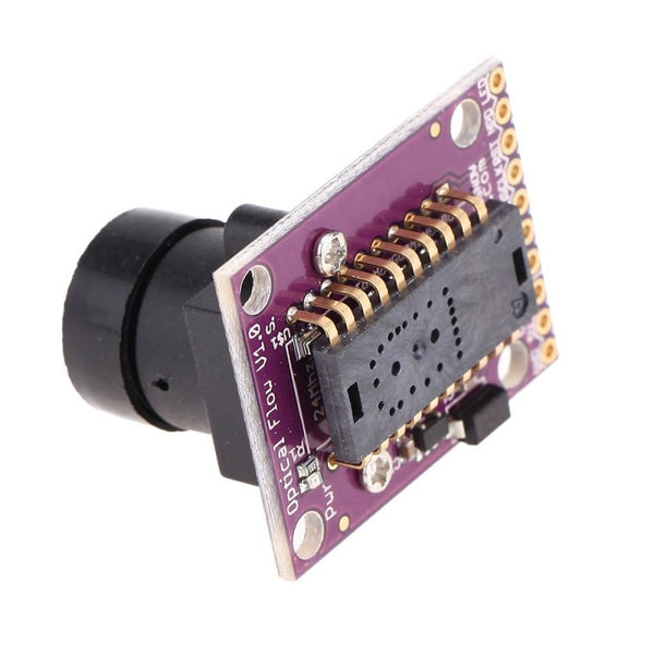
Introduction:
This sensor is based on the idea of optical mouse (image sensor). It senses the image (camera sensor) of a surface or an object by taking very large number of images (frames) in short time. ... Using build in image processing algorithm, then the displacement of the object can be defined.
Connections:
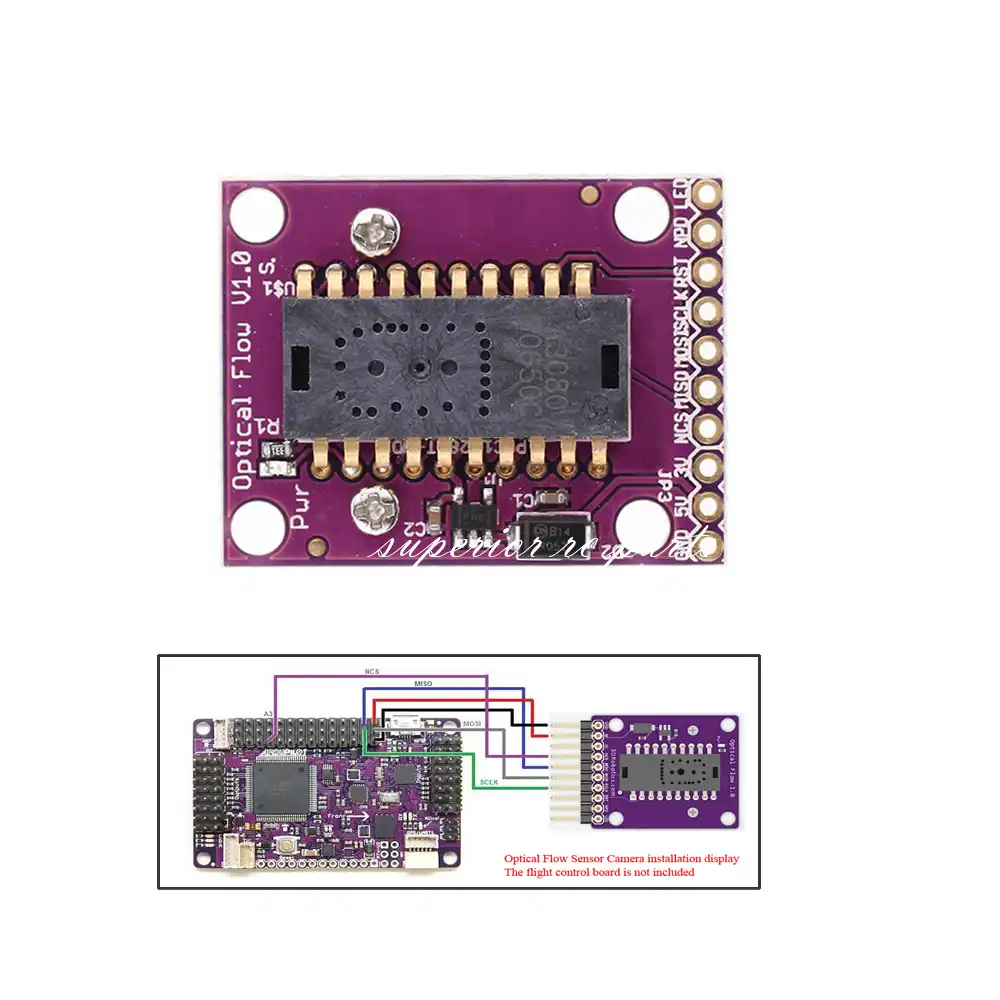
How it works
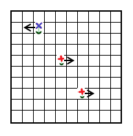
The mouse sensor returns the average movement (in the x and y directions) of surface features that it sees. A single pixel move will not cause the sensor to return “1”. It will return a higher value around 5. This value is referred to as the scaler below. In the example below, the value returned would be about 1.6 ( (-5+5+5) / 3)
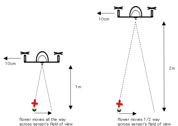
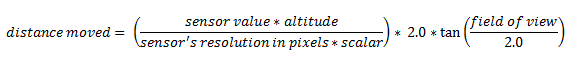
Sensor’s x and y values can be converted to real distances based on altitude
In order to convert values from the sensor to real distances moved, we need to take into account the altitude. This is necessary because as you can see from the two pictures below, if we have two quads moving the same distance, but one at a low altitude, the other at a higher altitude, the lower quad will see surface features appear to move further and this will result in a higher optical flow values
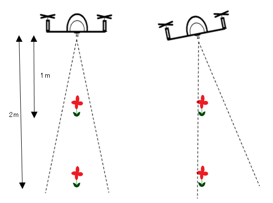
We compensate for vehicle roll and pitch changes
Change in the vehicle’s roll and pitch will also cause changes in the x and y values returned by the sensor. Unlike the lateral movement calculations these are not dependent upon the distance of the visible objects. In the picture below you can see that as the quad has rolled 10 degrees but both flowers have moved from the center of the camera’s view in the 1st pic to the edge of the view in the 2nd pic.
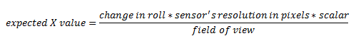
The expected change in sensor values can be calculated directly from the change in roll and pitch given the formula below. We subtract these expected changes from the real values returned by the sensor.
Once we have the x/y movements we can integrate these values over time with the current yaw to arrive at an estimate of position.